
Request a Quote
  • Affiliates

10 Tips to Choose the Right Festo Pneumatic Cylinder?

Choosing the right Festo Pneumatic Cylinder is not simply a matter of matching bore size to a machine drawing. The cylinder must produce enough force, fit the available space, and withstand its working environment. A packaging line may require clean, repeatable motion, while a dusty fixture may need stronger protection and simpler maintenance. Small details matter. A side load, long stroke, or poorly aligned rod can shorten service life. These problems often remain hidden during a quick catalog search.

This introduction outlines ten practical tips for selecting a suitable cylinder with greater confidence. It considers bore diameter, stroke length, operating pressure, speed, cushioning, mounting style, and sensor compatibility. It also examines air quality, temperature, corrosion risk, duty cycle, and available installation space. Festo technical datasheets and application information should guide the final decision, rather than assumptions based on appearance or brand familiarity. A qualified engineer should verify force calculations and safety requirements before installation.

A neat-looking selection can still be wrong. In practice, the best option is often not the largest or most expensive model. It is the cylinder that delivers stable motion without unnecessary capacity, energy use, or maintenance. I have seen specifications treated as minor details, especially when projects face time pressure. That shortcut deserves reflection. Testing the cylinder under realistic load conditions can reveal vibration, slow movement, or end-position impact before these issues affect production. The following tips provide a practical framework for comparing options and making a more reliable Festo selection.
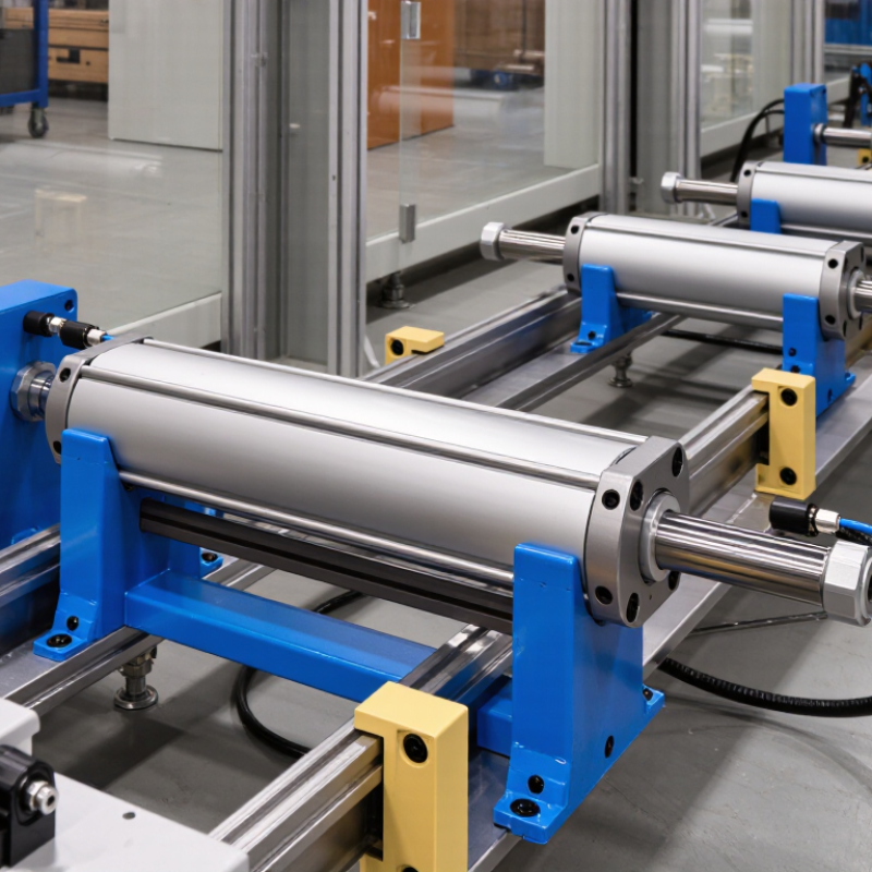
10 Tips to Choose the Right Festo Pneumatic Cylinder?

Understand Festo Pneumatic Cylinder Types and Operating Principles

Pneumatic cylinders convert compressed air into linear motion. A piston moves when pressure enters one side of the cylinder tube. In a double-acting cylinder, air controls both extension and retraction. A single-acting model uses air for one stroke and a spring for return. Compact cylinders suit short spaces, while guided cylinders resist rotation and side loads. Rodless designs provide longer travel without requiring extra rod clearance. Understanding these principles prevents many sizing errors.

Tip 1: Match the cylinder type to the motion. Tip 2: Check bore size against the required force. Tip 3: Calculate force with actual working pressure, not the compressor rating. Tip 4: Confirm the stroke length carefully. Tip 5: Choose cushioning for fast or heavy movement. Tip 6: Consider load alignment before installation. Tip 7: Use a guided style when twisting is possible. Tip 8: Verify port size and tubing length. Tip 9: Inspect seals in dusty or damp areas. Tip 10: Leave adjustment space around the cylinder.

In practical installations, friction, pressure loss, and uneven loads reduce theoretical performance. A cylinder that looks powerful on paper may move slowly under real conditions. I have seen designers overlook side loading because the first test worked without trouble. That decision later caused rod wear and unstable movement. Select mounting hardware, valve response, and sensors as one system. A small safety margin helps, but excessive oversizing wastes air and space. Recheck the calculation after observing the machine’s actual cycle.

Festo Pneumatic Cylinder Selection: Theoretical Extension Force by Bore Size

Choosing the right pneumatic cylinder starts with matching the bore size to the required load. The chart shows the theoretical extension force at 6 bar for common cylinder bores, calculated using the piston area formula: Force = Pressure × Area. Actual force may be lower because of friction, air losses, alignment, and operating conditions.

Selection tip: Consider cylinder type, stroke length, mounting method, speed control, side loads, cushioning, operating environment, and a suitable safety factor before selecting a pneumatic cylinder.

Define Load, Stroke, Speed, and Force Requirements

Choosing the right pneumatic cylinder starts with a clear load definition. Measure the moving mass, friction, mounting angle, and external resistance. A horizontal slide may need far less force than a vertical lift. At 6 bar, a 50 mm bore produces about 1,180 N of theoretical extension force. Real output is lower because of seal friction and pressure losses. I usually allow a practical safety margin of 25% to 50%, but this depends on acceleration and duty cycle.

Stroke must match the actual travel, not the available space. Add a small allowance for cushioning, alignment, and end-position tolerance. Excess stroke can increase bending risk and wasted air. Speed also needs a measured target. A cylinder moving too quickly may impact the end cap, while a slow cylinder can reduce production capacity. Flow controls, tubing length, and valve size all affect speed. Test the complete circuit, not only the catalog value.

Force calculations should include the return stroke. The rod reduces effective area, so retraction force is lower. This detail is often missed. According to the U.S. Department of Energy’s Compressed Air Challenge guidance, compressed air systems can lose 20% to 30% of compressor output through leaks. Poorly sized cylinders multiply that waste. The same guidance reports that compressed air may represent 10% to 30% of industrial electricity use. ISO 15552 dimensions can support interchangeability, but they do not replace load, stroke, speed, and force checks. My early estimates were sometimes too optimistic. A short trial with real pressure and load is safer than trusting theory alone.

Select the Correct Bore Size, Mounting Style, and Rod Design

Choosing a pneumatic cylinder starts with the load, stroke, and available space. Bore size determines pushing force, while pressure and friction affect real performance. Use force = pressure × piston area, then add a practical safety margin. Do not size from catalog photographs. A cylinder that looks adequate may stall when seals age or supply lines are undersized. I have seen this during commissioning. For vertical loads, include gravity and consider pressure loss. A slightly larger bore can improve reliability, but it may increase cost and air consumption.

Mounting style should match the movement, not just the machine frame. Clevis mounts suit pivoting loads, while flange mounts support rigid, straight-line installation. Trunnion designs can reduce side stress when the cylinder swings through an arc. Check alignment across the full stroke. Alignment matters. Even a small offset can bend the rod or wear the guide. Measure mounting faces with the cylinder retracted and extended. This detail is often missed. Also inspect maintenance access. A perfect mount is useless if technicians cannot remove the rear cap.

Rod design deserves equal attention. Choose rod diameter for buckling risk, unsupported length, and side loading. A larger rod is not automatically better. It can increase package size and reduce response speed. Stainless or coated surfaces may suit moisture, dust, or washdown environments. Match rod threads and end geometry to the driven component. Use external guidance when loads are not purely axial. I once focused too heavily on bore size and ignored rod alignment. Field testing exposed that weakness. Verify force, speed, cushioning, and mounting under actual operating conditions before approving the design.

10 Tips to Choose the Right Festo Pneumatic Cylinder? - Select the Correct Bore Size, Mounting Style, and Rod Design

Tip Selection Dimension Key Data or Rule Typical Reference Values Practical Selection Guidance
1 Required Thrust Calculate the theoretical extension force with: F = P × A, where pressure is in N/mm² and piston area is in mm². At 6 bar: Ø32 ≈ 482 N; Ø40 ≈ 754 N; Ø50 ≈ 1,178 N; Ø63 ≈ 1,870 N; Ø80 ≈ 3,016 N; Ø100 ≈ 4,712 N. Use the actual operating pressure and include friction, tooling weight, acceleration, and external resistance in the calculation.
2 Bore Size and Safety Margin Select a bore that provides more force than the calculated load. A margin of approximately 25% to 50% is commonly used for normal applications. If the calculated load is 600 N, a Ø40 bore provides about 754 N theoretical thrust at 6 bar before losses. A larger bore increases force but also increases air consumption, overall size, and cost. Avoid selecting the bore from load weight alone.
3 Operating Pressure Cylinder force is proportional to pressure, but the available plant pressure may fluctuate during peak demand. 6 bar = 0.6 N/mm²; 5 bar = 0.5 N/mm². A 10% pressure reduction produces approximately 10% less theoretical force. Size the cylinder using the minimum reliable working pressure rather than the highest possible compressor pressure.
4 Stroke Length Stroke is the distance the piston rod must travel to complete the movement. Common machine strokes include 25 mm, 50 mm, 100 mm, 200 mm, and 500 mm. Choose a stroke slightly longer than the required travel only when necessary. Excessive stroke can increase rod bending, cycle time, and installation space.
5 Mounting Style Mounting should support the cylinder without transmitting excessive side load to the piston rod. Typical options include front flange, rear flange, foot mount, clevis mount, trunnion mount, and tie-rod mounting. Use rigid mounts for straight-line loads. Use clevis or spherical joints where the mechanism pivots or alignment changes during the stroke.
6 Rod Diameter and Buckling Long, slender rods are more vulnerable to buckling under compression. Buckling risk increases with stroke length and unsupported load. For long compression strokes, consider a larger rod, guided load, reduced load, or a shorter unsupported length. Do not use the cylinder rod as a structural guide. Add external guides when the load creates bending, twisting, or offset forces.
7 Rod End Design The rod-end connection must match the motion, alignment, and load direction of the mechanism. Common designs include male or female threads, clevis ends, spherical rod eyes, and fork-style connections. Use a spherical connection for minor angular misalignment. Use a threaded rod end for simple axial force transfer with accurate alignment.
8 Cushioning and Speed End-of-stroke cushioning reduces impact energy and noise, especially at high speed or with heavy loads. Adjustable pneumatic cushioning is useful for variable loads; external shock absorbers may be needed for high kinetic energy. Use flow controls to regulate speed. Meter-out control is often preferred for stable motion when the load can overrun the cylinder.
9 Environment and Materials Temperature, moisture, dust, washdown, and corrosion affect seal life and material selection. Standard pneumatic designs are often intended for clean, dry air and moderate ambient conditions; special applications may require corrosion-resistant materials or seals. For wet or dusty areas, confirm the required protection, wiper design, lubrication method, and seal temperature range before selection.
10 Air Consumption and Cycle Rate Air consumption rises with bore size, stroke, pressure, and cycle frequency. For a double-acting cylinder, approximate free-air consumption per cycle is based on the extension volume plus the retraction volume, multiplied by absolute pressure ratio. Check valve capacity, tubing size, compressor capacity, and cycle time. A smaller bore may reduce air use, but it must still meet the required force and speed.
Calculation note: The force values shown are theoretical extension forces at 6 bar and do not account for seal friction, pressure losses, dynamic effects, or rod-side area. For final sizing, verify the cylinder manufacturer’s technical data and the complete machine load profile.

Check Air Quality, Environmental Conditions, and Material Compatibility

Selecting a pneumatic cylinder begins with the air entering it. Check the compressor system for water, oil carryover, particles, and unstable pressure. Moisture is deceptive. It may remain hidden until the cylinder stalls on a cold morning.

Use suitable filtration, drainage, and pressure regulation for the application. Confirm the required air quality from the equipment specification, not from guesswork.

In one workshop, condensation collected inside a poorly sloped airline. The actuator moved slowly, then failed to return fully. The cylinder was not the real problem. The air preparation was.

Environmental conditions deserve equal attention. Dust, washdown water, salt, heat, and freezing temperatures can change cylinder performance. Select corrosion-resistant surfaces and protection levels that match actual exposure. A clean indoor room and a dusty packaging line need different solutions. Measure temperature near the cylinder, because nearby motors can create hotter conditions than the general room.

Material compatibility is also practical, not merely chemical. Compare seal and tube materials with cleaning agents, process fluids, lubricants, and airborne vapors. Even a mild solvent can harden an unsuitable seal over time. Check rod coatings and mounting materials for corrosion risks. Test under load.

I prefer a short trial using the real pressure, cycle rate, temperature, and cleaning routine. Catalog data helps, but field conditions often disagree. I have overlooked vibration before, and the resulting side load shortened service life. Leave room for that kind of error. Record the test results and review them with the maintenance team before approving the final cylinder.

Compare Controls, Maintenance Needs, Safety, and Total Cost

Choosing a pneumatic cylinder should begin with control requirements, not catalogue price. Confirm the required stroke, force, speed, mounting space, and duty cycle. Then examine the control architecture. A basic directional valve may suit simple motion, while proportional control supports smoother positioning and reduced impact. Sensors also improve fault detection, but they add wiring, software, and maintenance points. Keep access practical.

Safety deserves equal attention. ISO 4414 requires pneumatic systems to manage unexpected movement, stored energy, and safe exhaust conditions. Include pressure regulation, suitable guards, and a controlled restart strategy. A small cylinder can still cause serious injury. Never assume low pressure means low risk. Maintenance planning should cover seal wear, rod contamination, tubing damage, and water in the air supply. The U.S. Department of Energy’s compressed-air sourcebook reports that leaks can waste 20–30% of compressor output. That makes leak testing part of cylinder selection, not an afterthought.

Total cost includes energy, downtime, replacement parts, installation, and technician time. The same DOE guidance notes that compressed air may consume about 10% of industrial electricity. A higher-priced cylinder with better sealing may reduce long-term waste. Yet this is not automatic. I have seen over-specified components create unnecessary complexity. Compare measured cycle demand, expected service intervals, and spare-part availability. Use real operating data where possible. Guesswork is cheaper only at the beginning.

en_USEnglish